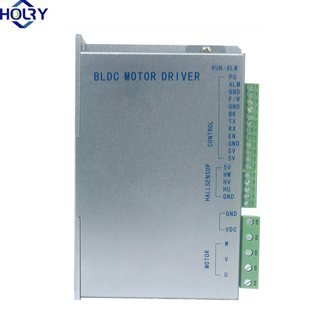
Function description of brushless motor driver
(1) Speed regulation mode
A. The driver is externally connected to a potentiometer for speed regulation.
B. Analog voltage speed regulation: You can connect the two fixed terminals of the external potentiometer to the GND and 5V of the driver respectively, and connect the adjusting terminal to the SV terminal to adjust the speed with an external potentiometer(10K~100K)
(2) Motor forward/reverse control (F/R)
Controlling the on-off of F/R and GND can control the running direction. When F/R and GND are not connected, the motor runs clockwise, otherwise, the motor runs counterclockwise.
(3) Enable(EN)
The on-off of the control terminal EN relative to GND can control the running and stopping of the motor. When connected to the GND terminal, the motor runs, otherwise, the motor stops running.
(4) Brake stop(BK)
Control the on-off of BK and GND to brake and stop. When the control BK is connected to GND, the motor stops and locks, and when it is disconnected, the brake stops, and the brake stop is faster than the natural stop. The specific stop time is related to the load inertia of the user system
(5) Motor speed signal output (PG)
Speed pulse output: The output frequency F(HZ) will be output between this port and the port GND. The relationship between F and the motor speed N(RPM) is as follows: F=N*P/60, where P is the number of pole pairs of the motor, that is, every output pulse is the number of pole pairs of the motor.
(6) Alarm output
Driver alarm output: When the ALM port alarms, this terminal is connected to GND (low level), and the driver stops working by itself and is in the alarm state.
 Русский
 English
 العربية
 Français
 Español
 Português
 Deutsch
 italiano
 日本語
日本語 한국어
한국어 Nederlands
 Tiếng Việt
 ไทย
ไทย Polski
 Türkçe
 አማርኛ
አማርኛ Bahasa Melayu
 தமிழ்
தமிழ் Filipino
 Bahasa Indonesia
 magyar
 Română
 Čeština
 हिन्दी
 فارسی
فارسی Kiswahili
 Slovenčina
 Slovenščina
 Norsk
Norsk Svenska
 українська
 Ελληνικά
 Suomi
Suomi עברית
עברית Dansk
Dansk বাংলা
বাংলা Hrvatski
 Afrikaans
 Gaeilge
 Eesti keel
 Māori
Māori සිංහල
සිංහල Azərbaycan dili
 Euskara
 Беларуская мова
 Български
 guarani
 Kreyòl ayisyen
 Kurdî
Kurdî Lietuvių
 Македонски
 తెలుగు