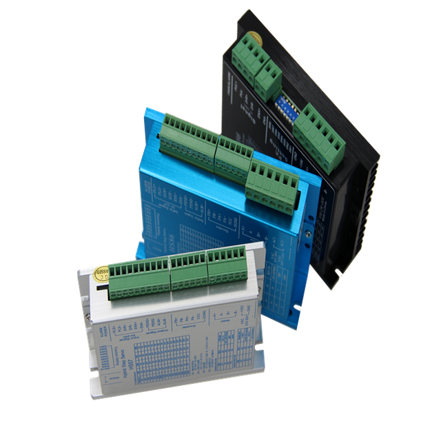
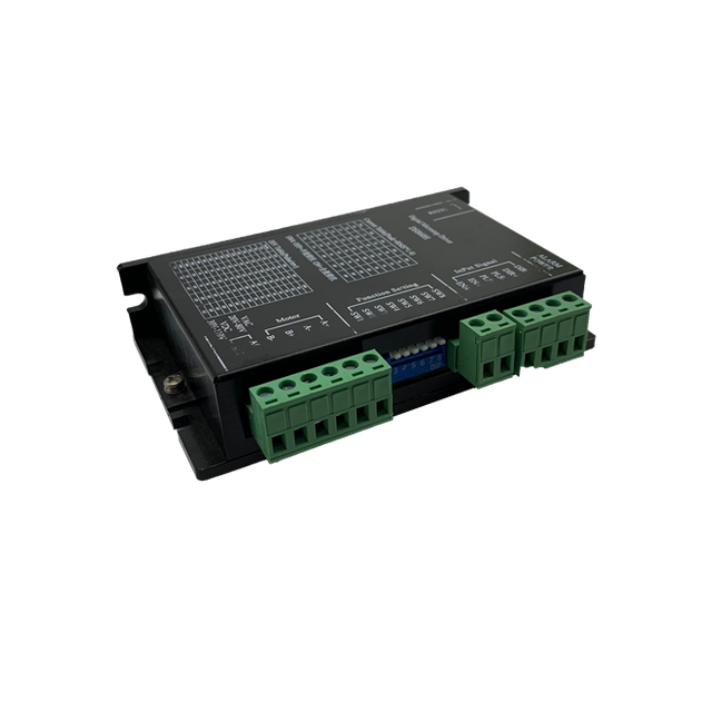
The HS57 Digital Hybrid Step servo drive
Product profile
1. summary
HS57 is the latest digital hybrid step servo drive with serial port debugging function launched by Core Internet of Things Technology Co., Ltd. It adopts the latest 32-bit DSP control technology and integrates MODBUS-RTU standard protocol specifications. Users can set multiple parameters such as 200-40000 through the upper computer debugging software, which greatly enriches the practical functions of the product and can meet the application needs in most occasions.
The HS57 drive adopts the control principle of servo class, which is compatible with the dual advantages of open loop step and servo system. It completely solves the problem of open loop step losing step, and greatly improves the performance of the step system, while reducing the heating and low-speed vibration of the motor.Compared with the servo system, it greatly reduces the difficulty of debugging, has the advantages of quick start and stop, stop without vibration, and its small volume, low cost and high cost performance, which can meet the applications in most occasions.
2. characteristic
● with serial port debugging function ● has a brand new 32-bit DSP technology
● small for easy installation
● can drive 4,6,8 line two-phase stepping motors
● light isolation differential signal input
● built-in microscopy
● subdivision set range of 200-40,000
● pulse response frequency of up to 200KHz (higher adjustable)
● current can be arbitrarily set up with the between the 0.1-3.5A to greatly
● precision current control to greatly reduce the motor heating
● low vibration low noise
● static current automatically halved
● has protective functions such as over-pressure, under-pressure and over-current
3. application area
Suitable for a variety of small and medium-sized automation equipment and instruments, such as: engraving machine, marking machine, cutter, plotter, CNC machine tools, automatic assembly equipment, etc.In the user expects small noise, high speed device application effect is particularly good.
Electrical, mechanical and environmental indicators
1. Electrical indicators
explain | HS57 |
least value | representative value | crest value | unit |
Enter the power voltage | 20 | 36 | 50 | VDC |
Control the signal input current | 7 | 10 | 16 | mA |
Step-in pulse frequency | 0 | - | 200 | KHz |
insulation resistance | 50 |
|
| MΩ |
2. Use the environment and the parameters
cooling-down method | Natural cooling, fan heat dissipation |
service environment | occasion | Can not be placed next to other heating equipment, to avoid dust, oil fog, corrosive gas, humidity is too large and strong vibration places, prohibit combustible gas and conductive dust |
temperature | 0——50℃ |
humidity | 40—90%RH |
vibrate | 10~55Hz/0.15mm |
Save the temperature | -20℃~65℃ |
3. Mechanical installation diagram
 Figure 1 Installation dimension diagram (unit: mm)
It is recommended to use side installation, better heat dissipation effect, when the design and installation size, pay attention to the terminal size and wiring!
4. Strengthen heat dissipation
1)The reliable operating temperature of the drive is usually within 50℃ and the motor is within 80℃;
2)It is recommended to choose the automatic half-flow mode, that is, when the motor stops, the current automatically reduces by half, to reduce the heat of the motor and the drive;
3)When installing the drive, use the side installation and form strong air convection on the drive bottom; if necessary, install the fan near the drive to form air convection, assist the drive heat dissipation, and ensure that the drive works within a reliable operating temperature range.
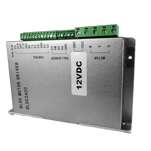
Introduction of drive interface and wiring
1. Interface description
1)Control signal interface
name | function |
P LS + | Pulse control signal: + 5V- + 24V can be driven, the rise line is effective, whenever the pulse, the motor steps from high to low.For a reliable response to the pulse signal, the pulse width should be more than 2s. |
P LS - |
DIR+ | Direction control signal: + 5V- + 24V can be driven, high / low level signal.To ensure reliable direction of the motor, the direction signal shall be established before the pulse signal for at least 5s.The initial operation direction of the motor is related to the motor wiring, and any interphase winding (e. g., A +, A-exchange) can change the initial operation direction of the motor. |
DIR- |
ENA+ | Enable control signal: + 5V- + 24V can be driven, high / low level signal.To enable or prohibit motor operation.When ENA + to + 5V and ENA-to low level, the drive will cut off the current of each phase of the motor leaving the motor in a free state when the step pulse is not responsive.When this function is not required, the enabling signal end can be suspended. |
ENA- |
2) Output signal interface
name | function |
PEND+ | In-place signal output: the motor reaches the position specified by the control command, and the in-place signal output is valid; PEND + connects to the pull resistance to the output source positive and PEND to the signal input of the controller; the maximum drive current is 50mA. |
PEND- |
ALM+ | Alarm signal output: over current, over pressure, underpressure or position differential alarm, alarm signal output is effective; ALM + connect to pull resistance to output power source positive pole, ALM-connect to signal input of controller; maximum drive current is 50mA. |
ALM- |
3) Encoder interface
name | function |
PB+ | Incoder B phase input interface, you should pay attention to the line sequence. |
PB- |
PA+ | Incoder A phase input interface, you should pay attention to the line sequence. |
PA- |
VCC | Main end of the encoder 5V power supply supply. |
EGND | Encoder 5V power supply power supply negative end. |
▶ Note: The wiring order of the encoder is noted on the bottom label of the closed-loop motor, strictly following the wiring on the label.
4) Strong power interface
name | function |
GND | DC power supply ground |
+V DC | Power supply cathode, range: DC 20~50V, recommended + 36V |
A+、A- | Motor A phase coil, Pay attention to the line order. |
B+、B- | Motor B phase coil, Pay attention to the line order. |
▶ Note: The wiring order of the motor is noted on the bottom label of the closed-loop motor to strictly follow the wiring on the label.
5) 232 Communication interface
The serial port communication interface driven by HS57 adopts the RJ12 terminal, which can be connected to the PC machine through USB to TTL serial port conversion tool. Live plug is prohibited!At the PC end, the customer can set the required parameters, such as current, subdivision, working mode, etc., depending on the upper computer software interface.
Terminal number | symbol | name | explain |
1 | GND | RS232 Communication | 0V |
2 | T X D | RS232 transmitting terminal |
|
3 | NC |
|
|
4 | R X D | RS232 receiving end |
|
5 | NC |
|
|
6 | NC |
|
|
▶ Note: The cables connected to HS57 and PC must be confirmed before use as special cables (randomly attached according to the user situation) to avoid damage.
6) Status indication
The green LED is the power indicator and the LED is on when the drive is on and the LED goes off when the drive is off.
The red LED is the fault indicator, which flashes for 3 seconds; when the fault is eliminated by the user, the red LED is often extinguished.Red LED flashes in 3 seconds represent different fault information, as shown in the following table:
order number | The number of flashing times | Red LED flashing waveform | Troubleshooting |
1 | 1 | | Overcurrent, alternate short circuit, or bad contact fault |
2 | 2 | | Overvoltage fault (voltage> DC50V) |
3 | 3 | | Undervoltage fault (voltage <DC20V) |
4 | 5 | | Motor open circuit (phase missing) |
▶ Note: Red LED is when alarm.
2. Control the signal interface circuit
Fig. 2 Input interface circuit
The differential signal circuit is used for the HS57 drive control signal end, which can be applied to the differential signal, one-end coYin and co-Yang interfaces, with built-in high-speed photoelectric coupler and strong interference resistance in cases of bad environment.A schematic diagram of the interface circuit is shown in Figure
▶ Note: The HS57 is a 5V-24V universal drive, so no serial resistance is required;
3. Control signal timing diagram
To avoid some misaction and deviations, P LS, DIR and ENA shall meet certain requirements as shown in the following figure:
FIG. 3 A control signal timing diagram
explanatory note:
1)The t1: ENA (enabling signal) shall be DIR at least 5ms in advance to be high.ENA + and ENA-suspension are generally recommended.
2)The t2: DIR at least early P LS decreases along 5s determines its state high or low.
3)The t3: Pulse width is not less than 2.5s.
4)The t4: Low level width is not less than 2.5s.
4. Control the signal mode setting
Pulse trigger edge selection: The pulse up edge or drop edge trigger can be set through the PC software.
5. Connection requirements
1)In order to prevent the interference of the drive, it is recommended to adopt the control signal shield cable, and the shield layer is short connected to the ground wire. Except for special requirements, the single end of the shield wire of the control signal cable is grounded: one end of the upper machine of the shield wire is grounded, and one end of the shield wire is suspended.Only the same ground in the same machine, if not the real grounding wire, may interfere seriously, when the shielding layer is not connected.
2)Pulse and direction signal line and the motor line are not allowed to be bandaged side by side, it is best to be separated by at least 10cm, otherwise the motor noise can easily interfere with the pulse direction signal to cause inaccurate motor positioning, system instability and other faults.
3)If one power supply is for multiple drives, a parallel connection should be taken at the power supply to one first to one chain is not allowed.
4)The strong electric terminal of the live unplug drive is strictly prohibited. When the charged motor stops, there will still be a large current flowing through the coil. The live unplug terminal will lead to a huge instantaneous inductive electric drive to burn out the drive.
5)It is not prohibited to tin the wire head to the terminal, otherwise the terminal may be overheated due to large contact resistance.
6)The wiring head shall not be exposed to the terminal to prevent accidental short circuit.
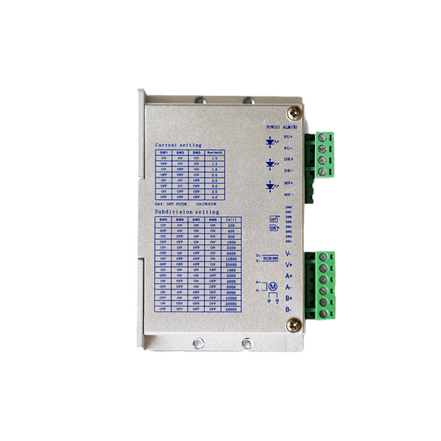
Dialup switch function setting
The HS57 drive uses a 10-bit dial-up switch, and SW1-SW4 is used for ALM, PEND output configuration setting, algorithm selection, maximum peak current setting, and direction selection; SW5-SW8 is used for subdivision setting; and SW9-SW10 is used for working mode selection.Details are described as follows:
SW1 | SW2 | SW3 | SW4 | SW5 | SW6 | SW7 | SW8 | SW9 | SW10 |
Function Settings | Subdivision Settings | Workmode Settings |
1. Function Settings
1)ALM, PEND output configuration settings
SW1 sets the output signal resistance of ALM and PEND, normally open either for SW1=OFF, and normally closed for SW1=ON.
2)Algorithm selection
SW2 is the control algorithm used for selecting drives, and algorithm A for SW2=OFF, and algorithm B for SW2=ON.
3)Maximum peak current setting
The SW3 sets the maximum output current of the drive, with a small current output for SW3=OFF, and a large current output for SW3=ON.
4)direction selection
SW4 sets the initial rotation direction of the motor, rotating in the positive direction when SW4=OFF; and reverse direction in SW4=ON.
2. Subdivision setting
Step number / turn | SW5 | SW6 | SW7 | SW8 | Section description |
400 | on | on | on | on | When SW5, SW6, SW7, and SW8 are all OFF states, the user can set any subdivision value of 200-40000 through the PC software with a resolution of 1. |
800 | off | on | on | on |
1600 | on | off | on | on |
3200 | off | off | on | on |
6400 | on | on | off | on |
12800 | off | on | off | on |
25600 | on | off | off | on |
51200 | off | off | off | on |
1000 | on | on | on | off |
2000 | off | on | on | off |
4000 | on | off | on | off |
5000 | off | off | on | off |
8000 | on | on | off | off |
10000 | off | on | off | off |
20000 | on | off | off | off |
40000 | off | off | off | off |
3. Working mode setting
SW9 | SW10 | Work mode selection | remarks |
OFF | OFF | Pulse + direction | When SW9 and SW10 are both in OFF status, the user can use the PC softwareSet up your own working mode. |
ON | OFF | Pulse + direction belt smooth processing |
OFF | ON | dipulse |
ON | ON | Spontaneous pulse |
▶ Note: Modineeds to be repowered to take effect.
Power supply selection
The power supply voltage can work normally between the specified range. The HS57 drive should preferably use non-stable DC power supply, or transformer voltage reduction + bridge rectification + capacitance filter.However, it should be noted that the rectified voltage ripple peak shall not exceed the specified maximum voltage.It is recommended that users use DC voltage below the maximum voltage to avoid grid fluctuations exceeding the operating range of the drive voltage.
If the voltage stable switch power supply is used, the output current range of the switch power supply should be set to the maximum.
▶ pay attention to:
1)Pay attention to the positive and negative power supply do not reverse connect;
2)It is best to use a non-stable type of DC power supply;
3)When using the non-stable voltage power supply, the power supply current output capacity should be greater than 60% of the set current of the drive;
4)When using a non-stable voltage switch power supply, the output current of the power supply shall be greater than or equal to the operating current of the drive;
5)To reduce costs, two or three drives can share one power supply, but should ensure sufficient power.
defencive function
1. short-circuit protection
In case of a alternate short circuit and an overflow inside the drive, the drive red light flashes once and flashes repeatedly in a cycle of 3 seconds.At this point, the fault must be eliminated and reset again.
2. overvoltage crowbar
When the input voltage is higher than the DC50V, the drive red light flashes twice and flashes repeatedly in a 3-second cycle.The fault must be eliminated and reset again.
3. undervoltage protection
When the input voltage is below the DC20V, the drive red light flashes 3 times and repeatedly in a 3-second cycle.The fault must be eliminated and reset again.
4. Lack of phase protection
When the current is initial, when the motor is phase, the driver red light flashes 5 times and flashes repeatedly in a cycle of 3 seconds.The fault must be eliminated and reset again.
5. Excess alarm signal
When an differential alarm occurs, the red light of the drive will remain on.The fault must be eliminated and reset again.
 Русский
 English
 العربية
 Français
 Español
 Português
 Deutsch
 italiano
 日本語
日本語 한국어
한국어 Nederlands
 Tiếng Việt
 ไทย
ไทย Polski
 Türkçe
 አማርኛ
አማርኛ Bahasa Melayu
 தமிழ்
தமிழ் Filipino
 Bahasa Indonesia
 magyar
 Română
 Čeština
 हिन्दी
 فارسی
فارسی Kiswahili
 Slovenčina
 Slovenščina
 Norsk
Norsk Svenska
 українська
 Ελληνικά
 Suomi
Suomi עברית
עברית Dansk
Dansk বাংলা
বাংলা Hrvatski
 Afrikaans
 Gaeilge
 Eesti keel
 Māori
Māori සිංහල
සිංහල Azərbaycan dili
 Euskara
 Беларуская мова
 Български
 guarani
 Kreyòl ayisyen
 Kurdî
Kurdî Lietuvių
 Македонски
 తెలుగు